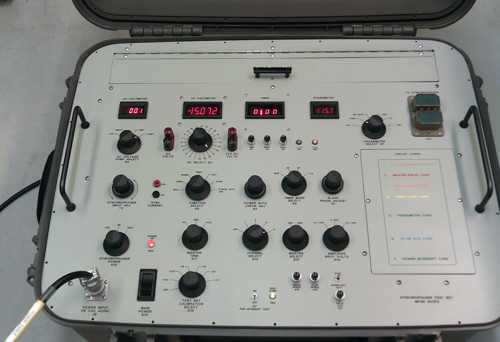
• SYNCHROPHASER TEST SET AD33510-4 equivalent

For 54H60 SYNCHROPHASER on C-130 Hercules, P-3C Orion Aircraft

• Part Numbers 761230-1/-2, 766840-1, 774800-1, 768950-5, 773170-3

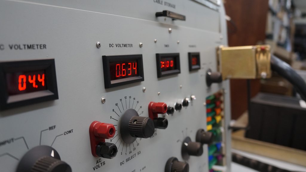
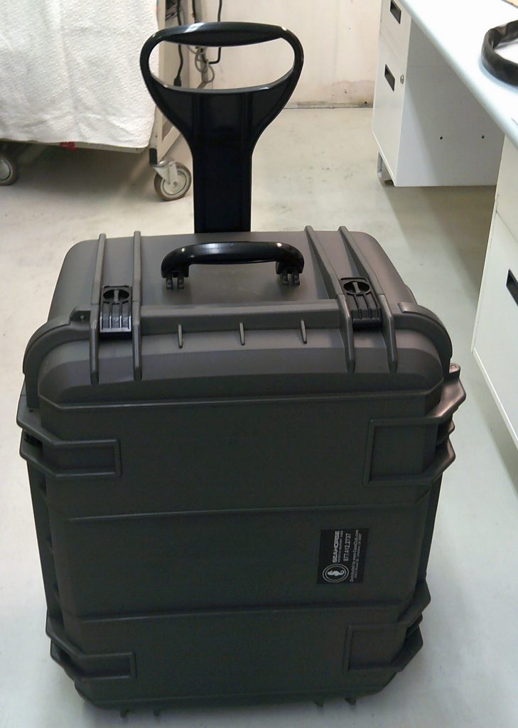
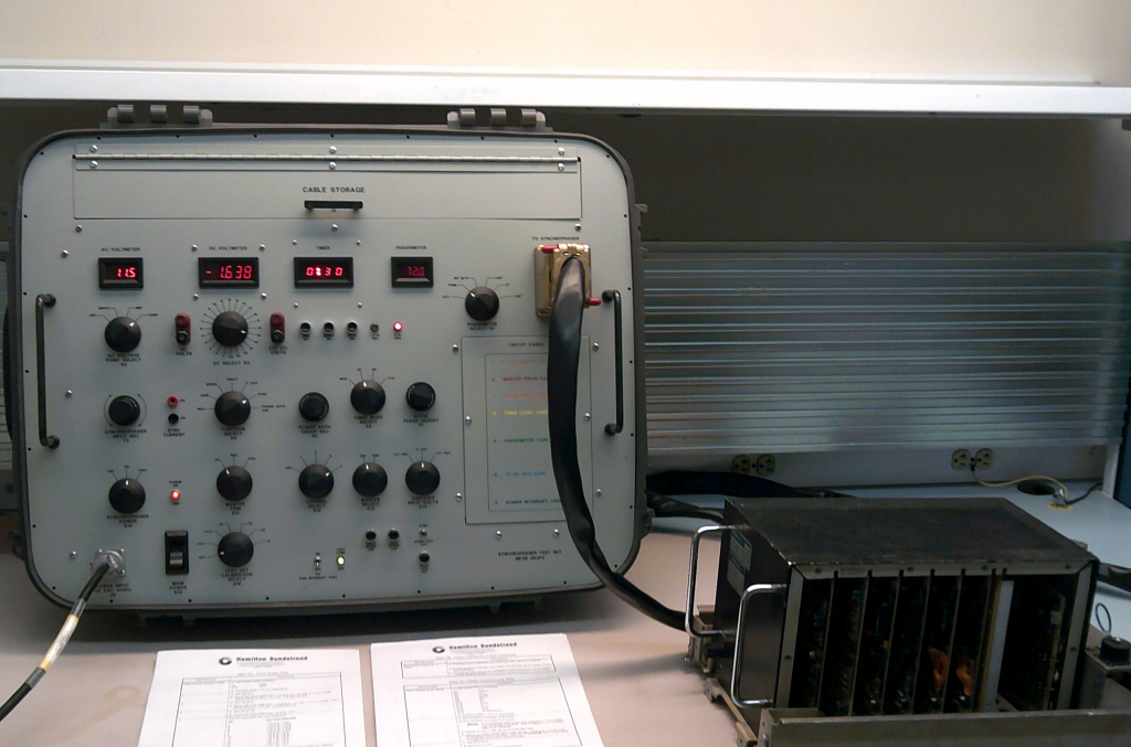
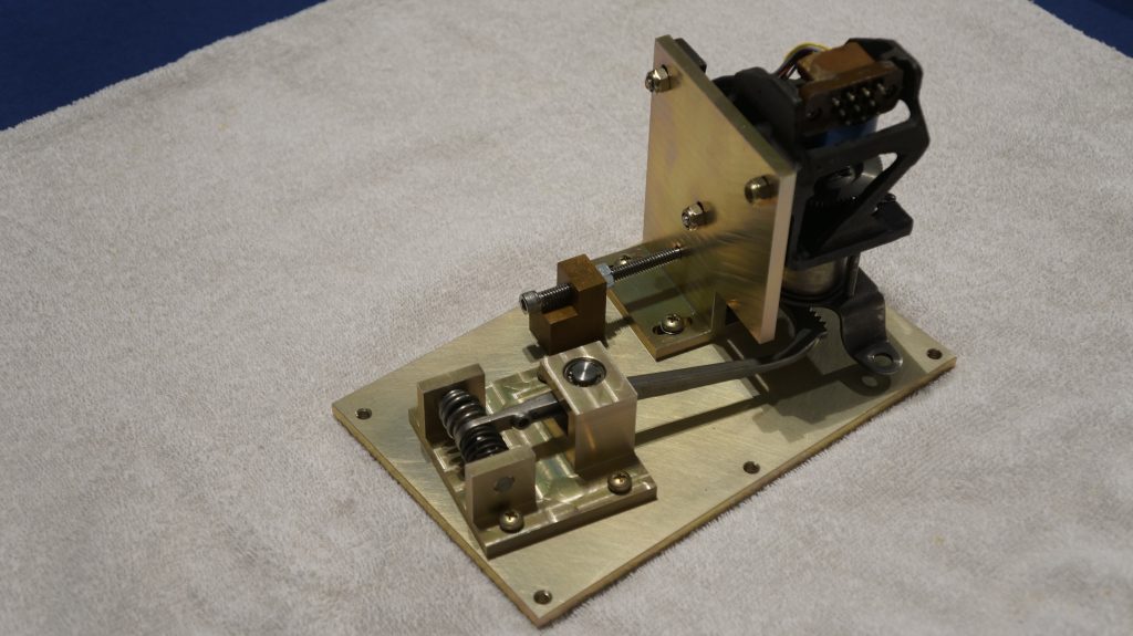
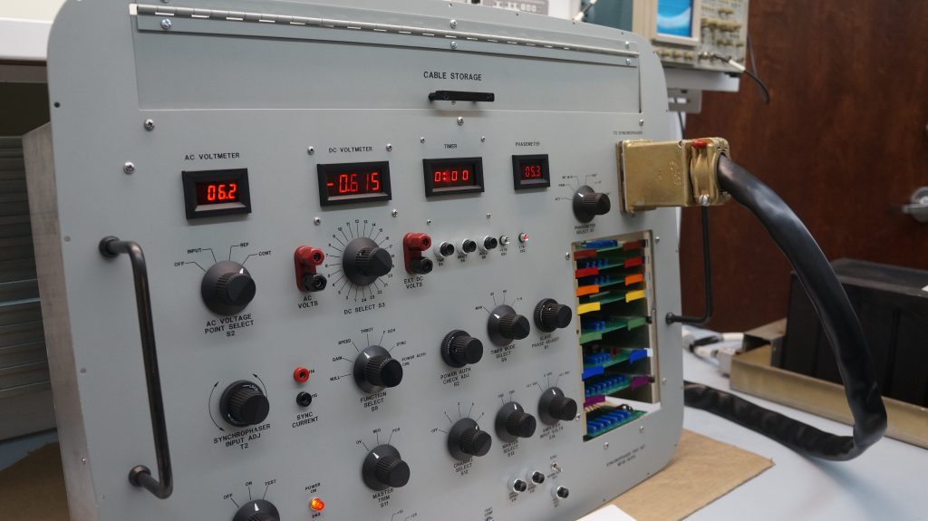
This is the most recent design and was a major project. It is based on the AD33510-4 test set originally manufactured by Hamilton Standard. My design has many improvements from the original AD33510-4 test set. It simulates the signals from the propellers, throttle control (power level position), engine rpm (tachometer). Checks master engine operation from engine 2 or 3 and engines 1, 2, 3, or 4 as a slave engine. Checks underspeed and overspeed conditions. Fuel Governor, Speed, and Throttle tests are checked. Power Interrupt tests along with the NORM/GOV and SYNC tests are accomplished. Repairs and overhauls of the C-130/P-3 Synchrophasers can be accomplished by testing and aligning the four Power Amplifiers circuit cards, Master Sync circuit card, and Double Slave circuit card. The test set includes the Speed Bias Servo assembly housed on the bell housing of the T56 engine. The Speed Bias Servo receives the output signals from either of the four power amplifier circuit boards and the motor moves in response to the outputs. The DC Voltmeter monitors the voltage outputs in accordance with rotary switch S3 selection. It has the Power Authority and Master RPM Trim test capabilities which are specific to the 768950-5/773170-3 Synchrophasers on the P-3 Orion. This test set has a total of thirteen printed circuit boards. The last photo shows the seven printed circuit boards that are accessible from the top of the test set. The unit is housed in a fiberglass case with easily transported handles and wheels. The power requirements are 115VAC 400HZ single phase.

The 766840-1, -2 and the 774800-1 Synchrophaser and Adapter assemblies replaced the 588584 tube-type Synchrophaser on the C-130 Hercules aircraft. The 773170-3 Synchrophaser and Adapter assembly replaced the 585500 tube-type Synchrophaser on the P-3 Orion aircraft.

These are the seven printed circuit boards accessible from the front of the test set. They are the following:

• 0.1 HZ Generator Circuit Card (Brown Ejectors)
• Master Pulse Generator Card (Red Ejectors)
• Slave Pulse Generator Card (Orange Ejectors)
• Timer Logic Card (Yellow Ejectors)
• Phasemeter Card (Green Ejectors)
• 70 HZ VCO Card (Blue Ejectors)
• Power Interrupt Card (Violet Ejectors)

IMG_20180830_124145601

THALES VERTICAL SPEED TCAS INDICATOR TEST SET

This is one of many of these test sets designed and manufactured to operate the Thales Vertical Speed Indicators part number series 457400. This test set has ARINC 565 vertical speed outputs: 26Vac REF and phase selected Vertical Speed output to indicator, ARINC 575 DC vertical speed outputs: + / – 12vdc REF and polarity selected DC output, lighting output voltage, remote light sensor inputs, and ARINC 429 inputs/outputs. This photo shows the test set in operation with the indicator at zero feet/minute showing intruder targets in the ARINC 429 High Speed TCAS test. The explanation of the five intruders are as follows:

• One is at 1000 feet above, no vertical rate, at 3.625NM, at -33.75 degrees from aircraft and is other traffic, (cyan diamond outline).
• One is at 1000 feet below, vertical rate descending, at 3.625NM, at +33.75 degrees from aircraft, and is proximity traffic, (solid cyan diamond).
• One is at 200 feet above, no vertical rate, at 2.0NM, +90 degrees from aircraft, and is a RA – resolution advisory, (red square).
• One is at 200 feet below, vertical rate climbing, at 2.0NM, -90 degrees from aircraft, and is a TA – traffic advisory, (green circle).
• One is at 3200 feet below, no vertical rate, at 2.5NM, at 180 degrees from aircraft and is other traffic, (cyan diamond outline).

The ARINC 429 signals were generated by an Excalibur DAS429Unet device using the Mystic software programmed to operate on the four ARINC 429 channels.
This printed circuit board was designed and used behind the front panel. By mounting all the toggle switches, tip jacks, and UUT valid lamps on this printed circuit board this eliminated all the wiring behind the panel and made for a cleaner and more compact project. Cutouts were made for the front panel mounted variable potentiometers, BNC jacks, lamps, and fuse holders.  A PC mount DL3-60R ZIF connector was used saving considerable construction time since two of these test sets were manufactured for the customer.
This printed circuit board was designed and used behind the front panel. By mounting all the toggle switches, tip jacks, and UUT valid lamps on this printed circuit board this eliminated all the wiring behind the panel and made for a cleaner and more compact project. Cutouts were made for the front panel mounted variable potentiometers, BNC jacks, lamps, and fuse holders. A PC mount DL3-60R ZIF connector was used saving considerable construction time since two of these test sets were manufactured for the customer.

HONEYWELL IVA-81A/81D VERTICAL SPEED TCAS INDICATOR TEST SET

This test was designed and manufactured to test and repair the Honeywell IVA-81A Vertical Speed Indicator part number 066-50001-XXXX and IVA-81D Vertical Speed Indicator part number 066-01171-XXXX

Bench testing a Honeywell IVA-81A TCAS Vertical Speed Indicator in ARINC 565 mode showing 1000 fpm increasing and TCAS intruders from ARINC 429 Simulator.

HONEYWELL BACKLIGHT CCA 4091889-1001 TESTER

This test set was engineered to activate the three separate LED Drivers on the Backlight Assembly 4091896-902. This unit is part of the 8-inch Honeywell Phase 3 Display unit part numbers 4091900-931 through -944. A common failure with this display is the backlight assembly. One or two LED strings fail rendering the display dim or unreadable. There are three LED lamp string circuits in the 4091889-1001 Driver assembly. This test set has three separate LED drivers on printed circuit boards housed in an electronic case. The digital panel meters monitor the voltage across each LED string and the current draw. The tester was engineered to operate the Backlight Assembly out of the display unit. It tests each LED lamp string separately and allows a technician to troubleshoot and repair the circuit card assembly removed from the 4091900- Display unit. One LED lamp string has 27 LEDs drawing a maximum of 1.4 Amperes, one LED lamp string with 26 LEDs drawing 1.4 amperes, and one LED lamp string with 109 LEDs drawing 70 milliamperes.

IMG_20180424_100527939
IMG_20180423_121945694 (1)

APQ-153 Fire Control Radar Antenna, Receiver-Transmitter, and Control

This test set was built for an avionics repair/overhaul shop to repair and overhaul the antenna, receiver-transmitter, and control for the APQ-153 and APQ-159 Fire Control Radar on the F-5E aircraft. It is identical to the test set part number 633175-303 that was manufactured by Emerson Electric Corp. This test set complements the Indicator and Processor Test Set part number 633176-307 also manufactured by Emerson Electric Corp.

APQ153RadarTS
APQ153TS2

Collins 329B-8J/Y Flight Director Indicator Test Set

This project was designed for a repair station to solve a high warranty problem. This test set exercises all the pointers, displays, and flags simultaneously similar to the actual aircraft operation. The Collins 980L-1 test set only tests each function individually. Several electronic circuits were designed to produce a slow and varying voltage that is adjustable in the upper and lower limit. One circuit to move the runway symbol in altitude, one to move it back and forth simulating the localizer deviation, another circuit drives the glideslope pointer up and down, another drives the speed command pointer up and down, another drives the rate-of-turn pointer, another drives the yellow command bar (V-Bar) in pitch, another circuit drives it in roll, and another drops the speed, glideslope, and rate-of-turn flags on and off at intervals of several seconds. A motor drive module was designed and built to move control transformers simulating the pitch and roll inputs from the vertical gyro. The circuit boards were designed, manufactured, and assembled with components. The front panel was designed to the customer’s requirement. The chassis box was assembled with the circuit boards, power supplies, and motor drive module. Two cables exit the rear of the test set and connect to the 329B-8 indicator. The scorsby table mounted on top of it met customer’s requirements to simulate the aircraft pitch and roll.

tmwimage3

TR5171 Audio Test Panel Printed Circuit Board

This PCB was designed per the schematic in the manufacturer’s maintenance manual. This audio panel used on the SAAB 340 aircraft.

IMG_20190510_152008201_HDR

Telephonics Audio Panel TS502-0108

This is the printed circuit board designed and manufactured per the schematic in the Telephonics Component Maintenance Manual for digital audio panel part number 502-0011 used on the SAAB-340 aircraft.

TelephonicsAudioPanel